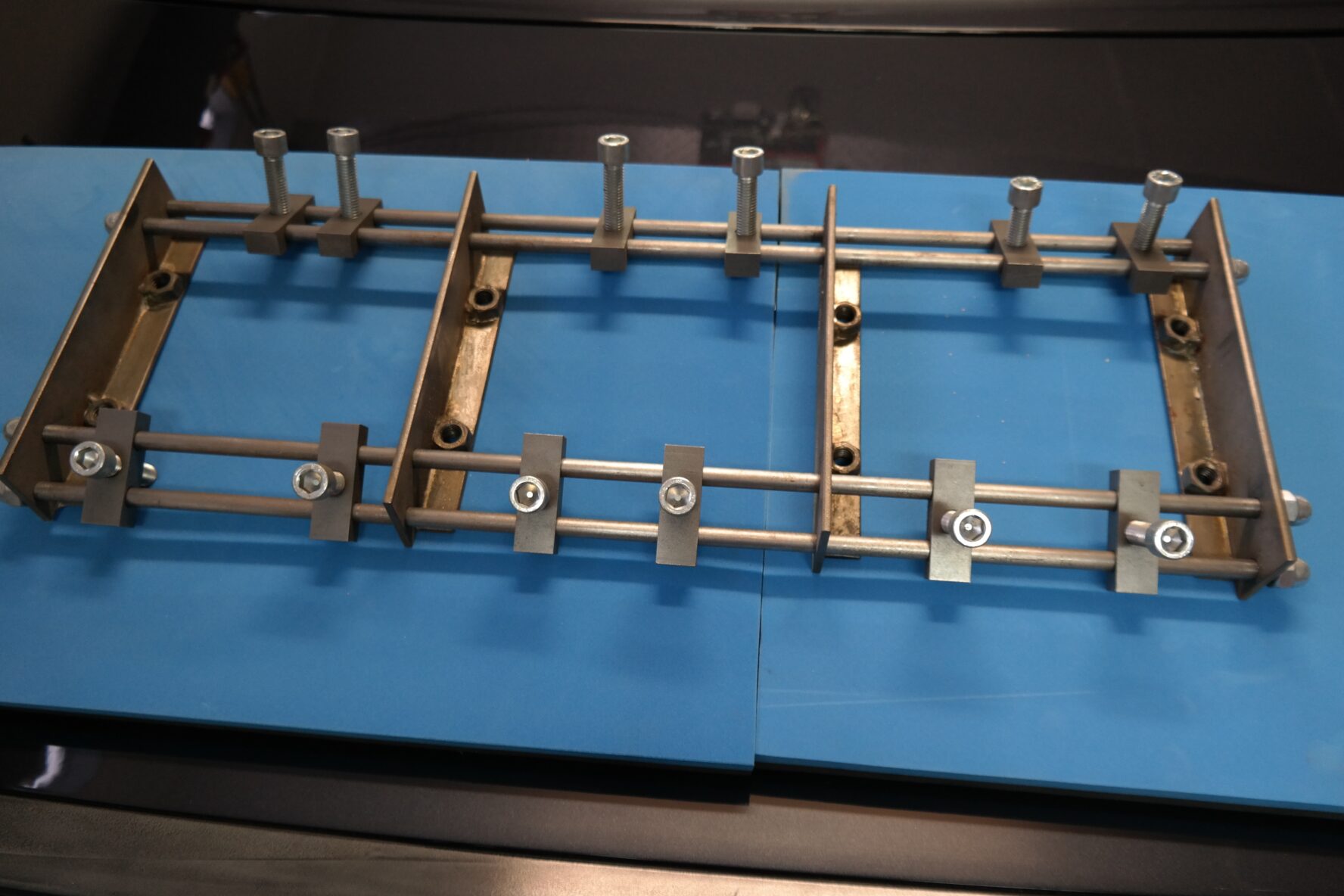
Although I’ve collected a lot of tools over the years of varying quality, it’s sometimes just not financially viable to spend money on certain special tools. My solution is to try and construct my own. When working on the BMW engine rebuild I found I needed to remove the camshaft from the head to get some machine work done. The factory tool, which seems to be quite well known by the BMW forums community, sometimes turns up on eBay for prices around $300-$400. As far as I know it looks like this and I believe it is known as the Iron Maiden.
Whatever – it never seemed like a serious piece of engineering to me so I thought I could do better. This is my take on it.
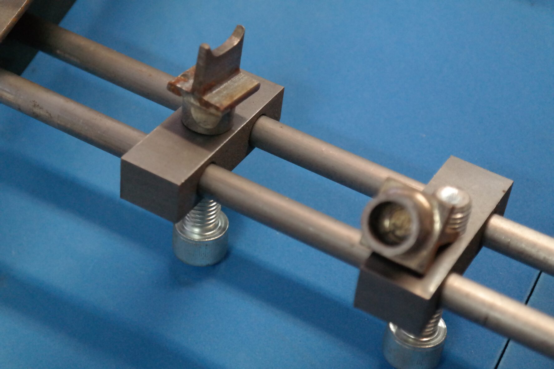
I generally store it like this but it can be completely dismantled. I started with some steel bar stock 50mm x 5mm and 20mm x 3mm. Cut this into 220mm lengths and drill the smaller strips with 12mm holes at 95mm centres leaving enough room to fit a 12mm nut snugly against the edge which will end up against the vertical strip. The bigger strips were drilled for the round bar stock rails they ride on with the centres of the lower hole 20mm from the bottom edge and 200mm between centres. The upper rail holes are at 30mm from the lower between centres (about a 20° angle from the lower) and 150mm between centres from each other. Note that these sets of holes need to be drilled as accurately as possible otherwise the assembly will bind. The pairs of strips were then brazed together at 90° and a 12mm nut was brazed over each hole in the smaller strip, as I said earlier the nut should fit snugly and makes for a neater braze. The rails are made from 10mm round bar stock, 650mm long, tapped at each end. I used acorn nuts to hold the assembly together but functionally standard nuts will do just as well of course. The blocks that also ride on the rails were fabricated from 20mm x 15mm bar stock cut to lengths of 60mm. Through the 20mm side they are (centrally) drilled and tapped 12mm for the bolts performing the spring compression. Through the 15mm side they are drilled 10mm to ride on the rails. Again these sets of holes need to be drilled as accurately as possible otherwise the assembly will bind. The bolts in the blocks are 60mm long and I used Allen heads purely because they look better. The next thing we need are a set of cups so that the bolts don’t damage the rockers when you are turning them.
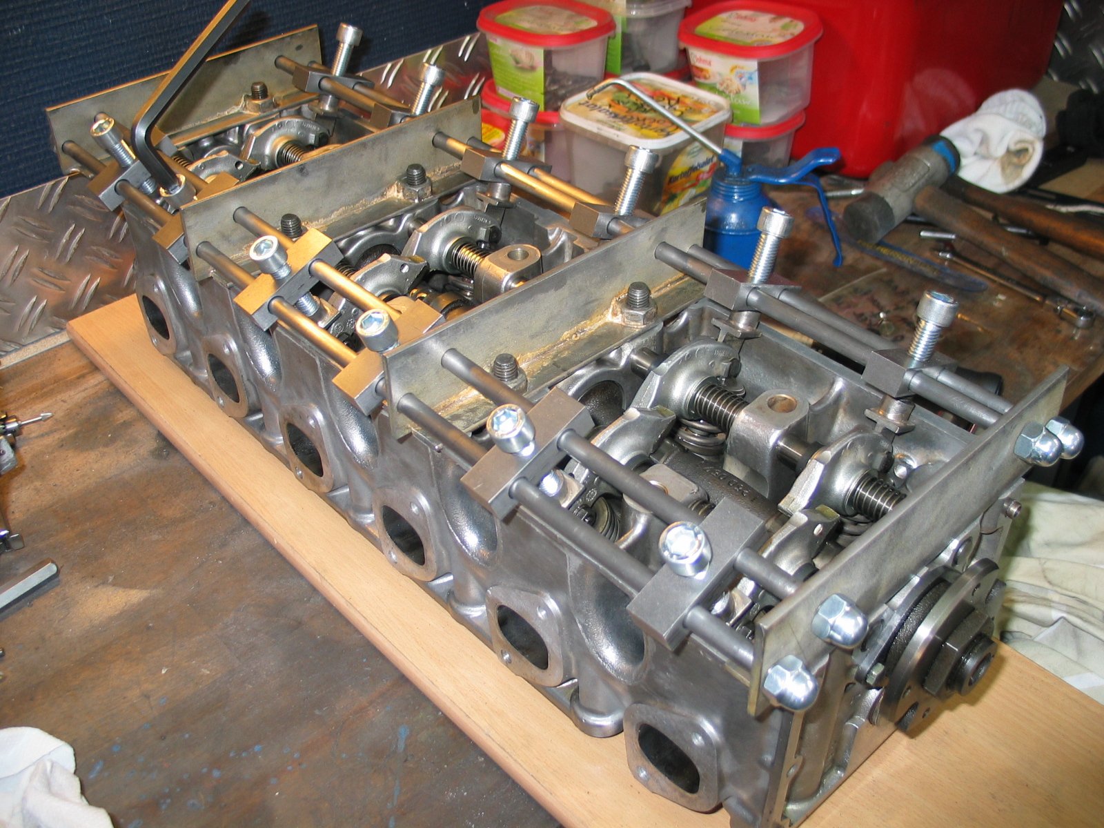
The cups are fabricated from steel tube 12mm inside diameter cut to lengths of 10mm. They are brazed to 20mm lengths of 20mm x 20mm steel T bar stock. The lower edge of the T is then radiused so that it rides smoothly on the eccentric visible through the split in the rocker arm. You’ll notice that the curve of the radius is elliptical because of the lateral movement of the rocker compared to the motion of the bolt as it compresses the assembly. This should be well lubricated during assembly. You may have seen this photo on the engine rebuild page but this is how it sits on the head.
You can’t actually see the underside in this photo but the bolts holding the main supports to the head through the nuts that were brazed to the smaller strips were packed out with a couple of thick washers giving enough room under the head to allow the valves to move without hitting the workbench. When all four supports are in place the blocks can be slid into place above the rocker arms and the cups put into place. It’s just a question of tightening up the bolts to compress the springs and rockers so that the cam is then free to be extracted. It will be noted by some that you don’t actually need to compress all the valves to remove the cam as not all lobes are loaded. In other words you can get away with only fabricating a few of the blocks but then you need to place them on the rails where you will need them depending on where the cam is sitting. I thought that while I was at it I’d just do all 12 and then I didn’t need to think about it, I could just compress all of them making extraction and insertion simpler.
If anybody in the BMW community in the Netherlands wants to borrow it please get in touch.


Nice work! Love the elegance of a nice simple design. Wish I was nearby. Been wrestling with pry bars, and rubber hammers today per the Bentley manual and getting ready to go buy a bunch of large c-clamps and overhead valve spring compression tools at Harbor Freight to get the cam out without damaging the internal bearing bores in the head casting.
Hi Dave. Thanks for the comment. Yes – shame that you aren’t nearby as the tool is actually for sale as I have recently stopped with the Bimmer hobby. Age started to creep up on me and after an accident last year I decided that it was time to stop crawling under cars. The six is gone and I am now working on an old Harley Shovelhead – much easier.
Is the tool still for sale? Asking as I am disassembling a M30B34 head myself and im located in the netherlands.
You have come up with my favorite version of this tool.
I want to fabricate one similar that can also attach to the cam cover bolts/studs.
However I am a little confused with the dimensions called out at the 50mm vertical strips for the 10mm rail holes. You say they are 250mm and 300mm apart, but the vertical strips were previously called out to be cut at 220mm. Did a typo sneak in on you?
I really appreciate you sharing your design with the BMW community.
cb