Cars

This work was undertaken in the winter stop period of 2015 and was initially one of the blog pages.

The second part of the winter work was more electricals, new alarm and replacing the Miller GENIII with their WAR programmable chip. I couldn’t decide what to tackle next but seeing as how the loom needed opening up to remove the old alarm stuff and put in the new, plus I had to connect the gauges with the senders, I started on the alarm first. I bought a Toad A101CL alarm on eBay last year from Southern Car Security and got it delivered to friends in England. I picked it up when we went over to visit. I chose the Toad as it was reasonably priced and seemed popular on various forums. Strangely enough I couldn’t find much in the way of reviews for stuff like this here in the Netherlands although I did find a couple of sites offering diy alarms reasonably priced. Miguel the owner of Southern Security was really helpful with the installation although he is really busy and a reply to the mail is sometimes the same day but sometimes a day or two later. I’ve not taken any pictures of the alarm installation as it would give the game away a bit if you see what I mean. Everything is neatly taped up in the loom or routed tidily under and in the dash. The installation itself went reasonably but finding the correct connections even with the BMW ETM (Electrical Troubleshooting Manual). If you don’t know of this Google it – you’ll need one for your exact model and year anyway. When I finished connecting it all up I got the necessary chirps from it but it kept giving me 3 when arming thereby informing me that either the doors, bonnet or boot were still open. I disconnected the bonnet and boot and found that the doors were working correctly but it took me a couple of evenings testing and tracing to work out what was wrong. Both bonnet and boot switches work, as with the doors, by grounding the switch connection, so that’s how I’d wired it up. However when closed (switch open) I was still getting a signal to ground. Eventually I found that the positive feed to the lamp itself was showing me a connection to ground except when the lights were on when it gave me 12v. I think BMW must use some sort of relay system which I haven’t bothered to delve into but I solved it by putting a 5A diode in both feeds. Problem 1 was now solved. Secondly the central door locking was not working and I eventually found the answer on a blogsite from another BMW owner. As I understood the ETM it was using positive switching but again due to the complexity of the BMW wiring system this was again wrong and after connecting the two alarm wires to earth, instead of the 12v feed, problem 2 was solved. Lastly I needed to adjust the ultrasonic sensor and so needed to get into the service mode, that took me a while to get right. Once in service mode you need to be pretty quick switching the ignition on and off to get it to work but eventually I got it to chirp and then proceeded to check everything including the ultrasonic sensor. That is now adjusted so that if the window is open it doesn’t go off until you stick your arm right in.

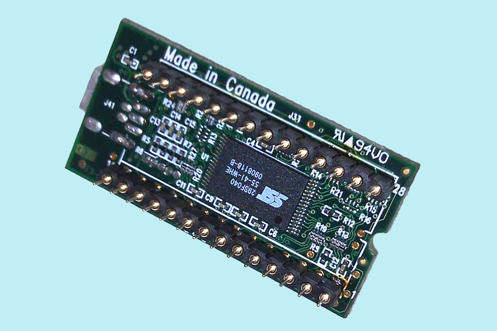
OK so the last part of the work was actually the easiest, installing the new WAR chip. Now the WAR chip is not actually a simple eprom like the oem chip or the GENIII, its a small printed circuit board with a set of pins through it to fit in the IC socket. It has a couple of larger chips and other components on it for the engine management, ram storage and the usb connection I presume.

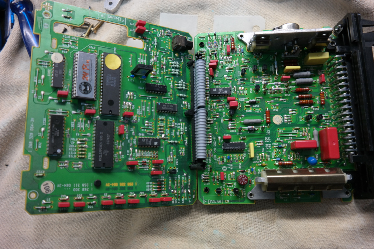
So the first job was to open up the DME casing and fold the hinged boards open to reveal the old GENIII chip top left, the silver one.

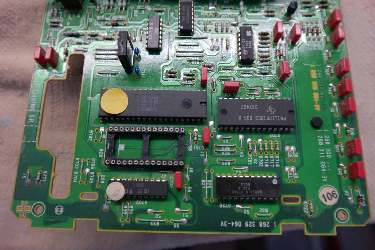
Once removed you can see the 28 pin eprom socket I installed when I did the original MAF conversion

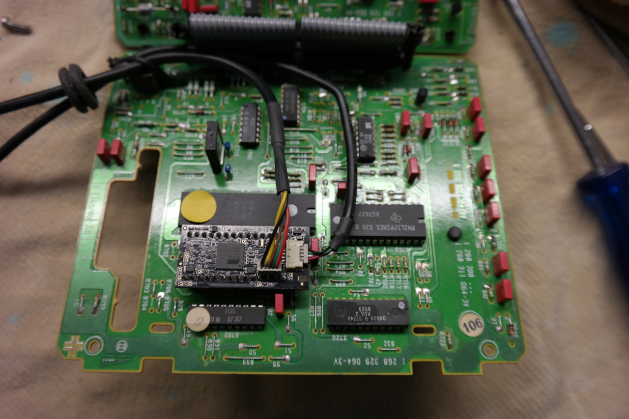
The WAR chip plugs in just like the old one. Here you can see the two supplied cables attached, the USB from the horizontal socket on the right and the cable for the tune selector switch from the vertical socket. Top left is a grommet round the cables to stop the casing chafing the cables.

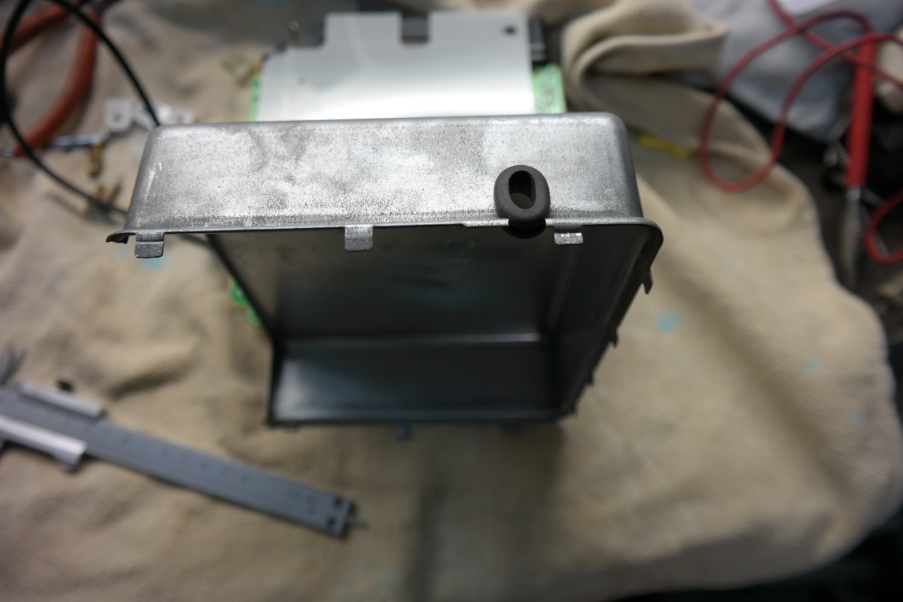
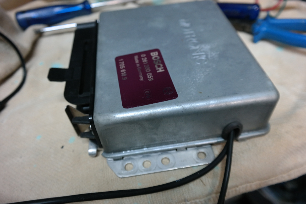
Here a shot of the casing with slot cut in it with the Dremel. Grommet takes on an oval shape in the slot to accommodate both cables snugly.

Once reassembled it looks like this ready to be refitted in the car.

The last job was installing Windows XP on an old laptop to use for the interface to the chip. The present WAR software won’t run on Windows 7 or later.

Next: New MAF Sensor

New Instrument Panel

This work was undertaken in the winter stop period of 2015 and was initially one of the blog pages.

Before Christmas I was busy doing some online shopping to get hold of the gauges and the Miller WAR programmable chip. The Toad Alarm system I bought last year when we were in England. The set of gauges included an oil pressure gauge, oil temperature gauge and a volt meter but after the WAR chip arrived I decided to get an AEM Wide Band UEGO O2 sensor and gauge to help me with the chip programming (it measures the fuel/air ratio), So after everything arrived I first set about stripping out the old alarm and the wiring behind the centre console for the radio which was also in a bit of a state from previous owners. I had been thinking for a while about a design to fit the gauges in the lower part of the centre console where the original cassette holders were situated. I also decided to replace the ashtray and lighter which are situated in the horizontal section in front of the cassette holder. After removing these sections I made templates from some cardboard packaging.

From the two templates I created a single section from MDF to fit in the space.

After a certain amount of adjustment and trial and error I got it to fit reasonably but not quite as I wanted it. The two holes were just to put my finger and thumb through to pull it into place. Not being completely happy I decided to remove the centre console completely, making access from the rear much easier than the turn and twist from the front.

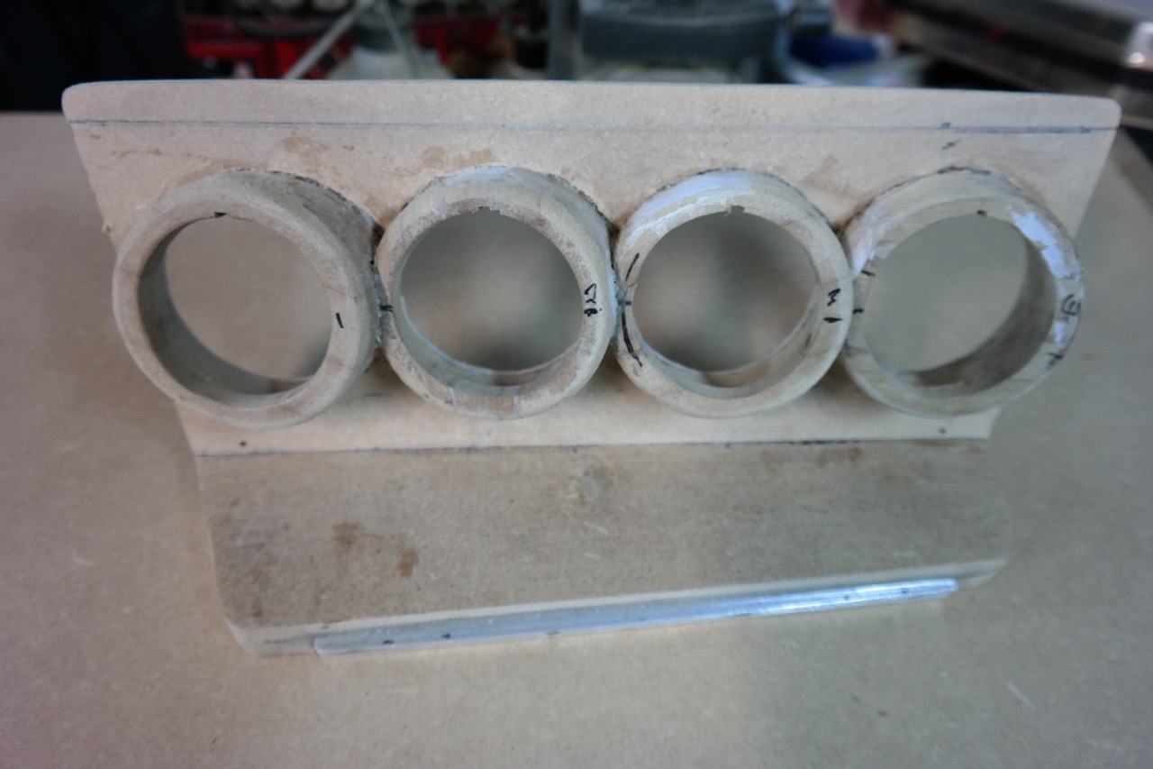
The next step was the the fitting of the gauges. It would have been simple to just cut some holes in the panel and job done but I had earlier realised that the visibility wouldn’t have been brilliant as they sit so low. They needed to be turned slightly upward and to the left and I first thought about making square box like sections to attach to the front. After playing around with a cardboard mockup I decided that it looked bit naff and decided to try and do something like the windscreen post pods which are available. What I needed was an MDF tube but nothing like that is available so I had to make my own. Step 1 glue some pieces of MDF together and let it dry overnight (sorry, too busy, forgot the photo’s again). Step 2 find the centres at the two ends and mount it in the lathe. Step 3 turn it into a solid cylinder. Step 4 divide it into four sections and using a fine blade as it turns in the lathe cut partly through each of the three cuts, finish the cuts off the lathe. Step 5 hollow out each section to the diameter necessary to allow the rear attachment, and here’s a photo (the duct tape is just to protect the surface a bit from the chuck jaws).

The mole wrench attached to the bed is just a quick fix to create a stop for the carriage so that I left the correct lip thickness to mount the gauge in place. The next photo shows a couple of the pods after completing this step. You can see the material left on what would be the front.

Step 6 is to put the pods back in the lathe and finish off the front so that the gauge fits. Round off the edge with some sandpaper to create the correct shape and the lathe work was finished.

Step 7: Create the correct angle to the back of the pod plus the shape to fit them together on the belt sander (again no photo’s, too much mess). Step 8: place the pods together on the front of the replacement lower panel and draw round them with a fine tip marker. Step 9: I machined around the inside of the marked lines on the milling machine to about half the thickness of the panel. All done slowly by hand as it’s not a CNC. This was done to create a better bond between the pod and the panel. After glueing and holding in place with some duct tape to dry overnight it looked like this.

Just a question of finishing now. After cleaning the glue off it started to look like it might be something and I made a start at getting it into shape with some polyester filler.

The back needed some extras to help mount the cigarette lighter (on the left) which I decided to keep rather than build in just a USB adapter. Also the control for the sub woofer and the rotary switch for the WAR chip tune selection. I needed to sink the knobs because the shafts wouldn’t fit on the 5mm thickness of the panel. Best solution seemed to be the aluminium strip which doubled as extra support for the sub control.

After priming plus liberal coats of spray filler and much sanding we were getting there.

A last trial fitting before some colour was applied and it was beginning to look like what I’d seen in my mind’s eye.

The initial result after spraying with matt black just didn’t look right, for one thing the paint wasn’t matt it had a slight shine which just didn’t look right with the rest of the dashboard. I ended up creating a textured finish by blowing some of the sawdust I’d created onto the wet paint and as it dried brushing off the excess.

After a bit of judicial work with some Scotchbrite it eventually seemed to be part of the interior. This is what it will look like when it gets replaced in the car although the console will need a bit of a polish of course.

After all that the workshop needed a lot of clearing up so I spent one evening with the vacuum cleaner, broom and dustpan and brush so I could begin with the electrics. Below you can see that I’ve been busy making a mini wiring loom which will attach to the rest of the electrics under the dash with the multi-plug. A few more wires to attach but it’s as good as finished and I can move on to the next job. Haven’t made up my mind if that’s going to be the alarm or the WAR chip upgrade.

Post Script: Wasn’t very satisfied with the Equus gauges I initially bought – cheap doesn’t cut it. So I bought a set of VDO and sold the Equus set.

Next: Alarm and WAR chip installation

The Scimitar was produced by the Reliant company in Tamworth, England between 1964 and 1986. The earlier 2-seater GT was produced up until 1968 when the 4-seater GTE was introduced. The first version, the SE5, ran until 1972 when it was superceded by the SE5A. The SE5A had numerous cosmetic changes compared to the early model and a slight power increase for it’s Ford 3 Litre V6 Essex engine. The SE5A can be recognised from a SE5 at the rear by the reverse lamps which are below the bumper on the earlier model and are incorporated into the rear clusters on the later version. There were 4,311 SE5’s built and 5105 SE5A’s.

The SE6 was introduced in 1975, it was more of a luxury model compared with the SE5 and was aimed at the executive market. It was longer and wider to give more room inside and is recognisable from the SE5 by the larger outside headlights. There were three model changes, SE6 (1975-76), SE6A (1976–80) and SE6B (1980–86). It had the same engine as the SE5 until Ford stopped production of the Essex engine, thus the introduction of the SE6B which used the Ford 2.8 Litre V6 Cologne motor as used in the Capri.

The Scimitar’s main claim to fame was that an SE5 was given to Princess Anne for her 20th birthday, she went on to own eight other GTE’s.

This ’73 Scimitar GTE (SE5A) was restored by me in the early 80’s when we lived in England. I sold it when we moved back to the Netherlands as I initially had nowhere to store it. Apart from that it was a right hand drive which is OK for a short holiday in the rest of Europe but not really ideal to keep.

On the Côtes d’Azur

I have no complete photographic history of the work as it was always a bit hit and miss with my use of the old film cameras. I did take these shots of the body after I’d removed the complete interior, all glass and all chrome work.

There were a couple of patches on the fibreglass body that needed the correct attention after I’d removed the filler used in the past. Some chrome parts needed rechroming and the whole interior needed some renovation. We (wife and I) re-covered the seats, fitted new carpets and refitted the headlining which was sagging. Outside it needed a complete respray and the vinyl roof needed some attention. The chassis (fibreglass body does not work as a monocoque) was in good condition so I decided not to do a body off, just did some cleaning and applied some underbody coating. I did pull the engine and after flushing, it was stripped down. It didn’t need a rebore so I just honed it, fitted new rings and bearings and put it back together. The heads were also in good condition so I just cleaned the valves and combustion chambers, fitted new valve seals and reassembled. With the heads re-installed with new gaskets the engine was given a fresh coat of paint and hung back in. The Weber 38DGAS received a rebuild kit just to be sure that it was functioning correctly. New plug leads and waterpump and it was beginning to look like it was earlier in it’s life (shame no photo’s). If you look carefully at the wheels on the old compared to wheels on the new you can see that the necessary elbow grease was applied here as well. Finally a set of old style number plates and we were ready for the owners club meetings, although I could probably go into fine detail about some of the other build and finishing work, without photo’s a bit pointless. Later it received a complete hand built stainless exhaust system bought through the owners club.

The car was never a trailer queen and although not a daily driver was used at least weekly. As a truck driver I didn’t use it through the week but my wife did sometimes. It was also used for holidays pulling a caravan that we had at the time. The picture at the top of the page was taken along the coast of the Côte d’Azur when holidaying in France. Below a photo of the car with caravan after visiting the Hostellerie Château des Fines Roches in Châteauneuf-du-Pape, Vaucluse.

Hostellerie Château des Fines Roches in Châteauneuf-du-Pape

We had just purchased a case of Châteauneuf-du-Pape (my personal favourite of the Rhône wines) and if I recall correctly had paid about 30 francs a bottle. On the menu of the gastronomic restaurant at the castle they were charging around 200 francs a bottle, and I thought we got a good deal at the time, it was definitely more expensive in England at the time. Today they have a bottle from 2010 for €60.

Below – overnight stop somewhere along the way at a municipal camping, always very cheap and near to the centre of a small town where there are always good restaurants to be found.

Municipal camping

After starting to strip it down I found that the factory sunroof was completely rotten and unrepairable, the only answer was a new roof. So a new roof was sourced from a scrap yard and the delicate process of cutting off the old one was started. The photo’s also show just how little room I had in my garage at the old house, the car only fitted if the nose went under the workbench.


Before cutting the old roof the car was supported on two thick wooden beams running the length of the car on each side, some careful measuring was necessary to ensure that the new roof fitted in exactly the same position as the old.


Most of these pictures were taken with an old polaroid camera which I had lying around, or a small 35mm Canon compact, so the quality is not that good and they are all quite small format. Here are a couple of close ups of the roof work.


The pillars are all braced behind the weld with pieces cut from the profile from the old roof giving some extra strength and also something to weld against. Shame there are no Photo’s to show it. After welding the centre pillars the beams were removed from under the car to put it back on it’s wheels. This pushed the front and rear pillar halves together so they could also be welded, this recreated the structural integrity of the roof.


That completed I moved on to the front end which was completely stripped out and all surface rust removed. If you look carefully you can see that it is sitting on the modified lower section of an old damaged shopping trolley. The reasonably sized caster wheels made it possible to push the shell in and out of the garage to work on it.


Again no pictures of any of the work after this until I’d finished the front end and was just about ready for the engine to be refitted.


It is still sitting on the trolley but the struts have been re-installed.


Having made plans to get much more power out of the engine than it had ex factory (would you believe that 140hp was all it produced!!), I had sourced a totalled ’87 Mustang GT at a breakers and got a good deal on the transmission (Borg Warner T5), rear axle with LSD, springs and brakes (bigger than my originals). The shocks were changed to Koni’s all round and all suspension rubbers were replaced with polygraphite bushes which give much better stability at the sacrifice of ride comfort. Goodridge brake lines all round as well. Another leap in time to the rear axle which was done in a similar fashion with the front wheels back on and the trolley supporting the rear.


The original rear suspension arms were replaced with Southside Machine Lift Bars to get that bite necessary for drag racing. Yes by this time the project had started to snowball into a near full blown drag car, at least as far as it was possible within the law in the Netherlands for a road going car. These bars have NO rubber bushings but instead steel bearings giving incredible straight line stability but again sacrificing ride comfort.


Next: Mustang – Part 2

Plastic nose masked up whilst the primer was applied. Did all this work in the covered area just outside my garage box until the Environmental Police paid me a visit – OOPS!


Black mist coat applied to aid with wet sanding of the primer. We needed a nice flat base for the colour.

Plastic nose had been primed earlier with a special flexible paint and then the black applied to the grill and bumper areas. The areas with the beige colour would be later sprayed blue with a flex agent when the car went to the paint shop across the road.

The car after the paint shop had finished with it and I had done the final interior build. The hood scoop is not original and was fabricated by me. Here it was running on a set of cheap Chrome Steel rims.

The under hood aluminium construction was also fabricated by me and gives a better flow of cooler air to the intake. The hot air generated by the headers and the larger radiator efficiency is not good for developing horsepower as the air is less dense, contains less oxygen and therefore can burn less fuel.

View of the interior. Originally all the plastic panels were a baby blue with fake wood dashboard panels, here they have been spray coated with a special plastic paint in a blue/grey colour. The fake wood panels were replaced with anodised aluminium and the original multi instrument block was replaced with separate gauges. On the top of the dash is an Auto Gage Shift-lite tachometer, when you reach the optimum r.p.m. a red light goes on telling you shift up. The original front seats were replaced by a pair out of a Saab 99 sourced at a local breakers. They were recovered in black leather by my wife who was working at a local upholsterer’s at the time. The original rear seat was recovered in the same leather. A set of 3 point racing harnesses were fitted in the front making use of the rear seat difficult to say the least. I also installed a cassette radio and some decent speakers but this turned out to be a bit pointless as it was difficult to hear the music above the sound of the engine.

This picture was taken a couple of years later when I had saved enough to order a set of Centerline alloy wheels from the USA.

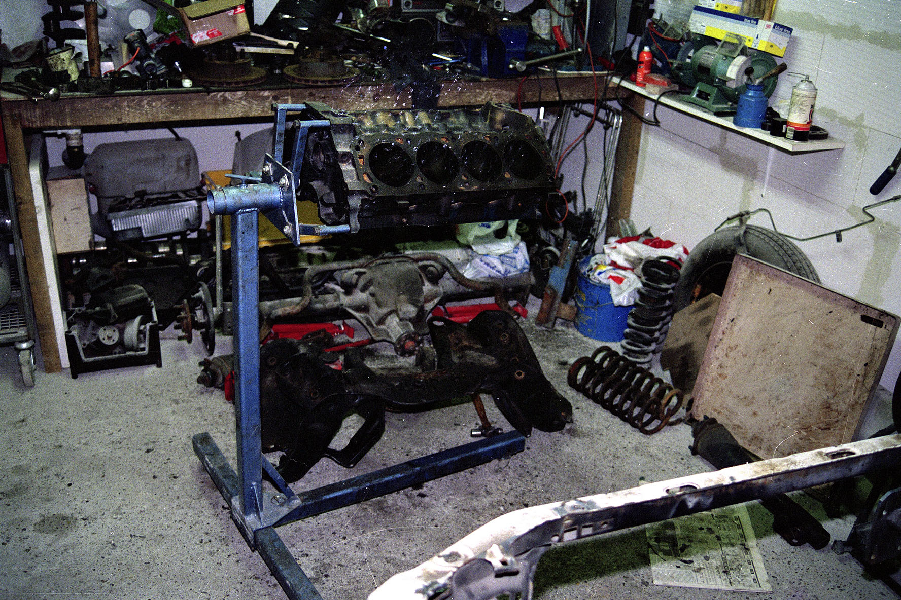
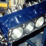
It was a bit of a puzzle to get everything to fit in the garage after I had stripped the car. Here you can see the block stripped down on the engine stand with rear axle and front subframe on the floor under the bench.


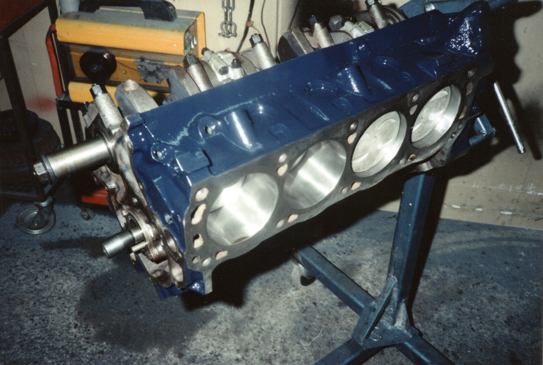
I eventually found a machine shop in Heemstede who knew what I was talking about when I told him that I wanted the block not only bored but align honed. He also individually honed each new piston to match each cylinder bore plus he had a contact who dynamically balanced the crank, rods and pistons. I took the heads with me when we went on a visit to friends and family in Northampton, England as one of my old mates worked at a good machine shop where the heads were skimmed, the valve seats equalised and a three angle valve job was machined. He also had an “old school” contact who specialised in head work and gasket matched the intake manifold and heads, and did some porting to improve the gas flow. Unfortunately no pictures of any of this early work, the following picture is of the block during assembly.


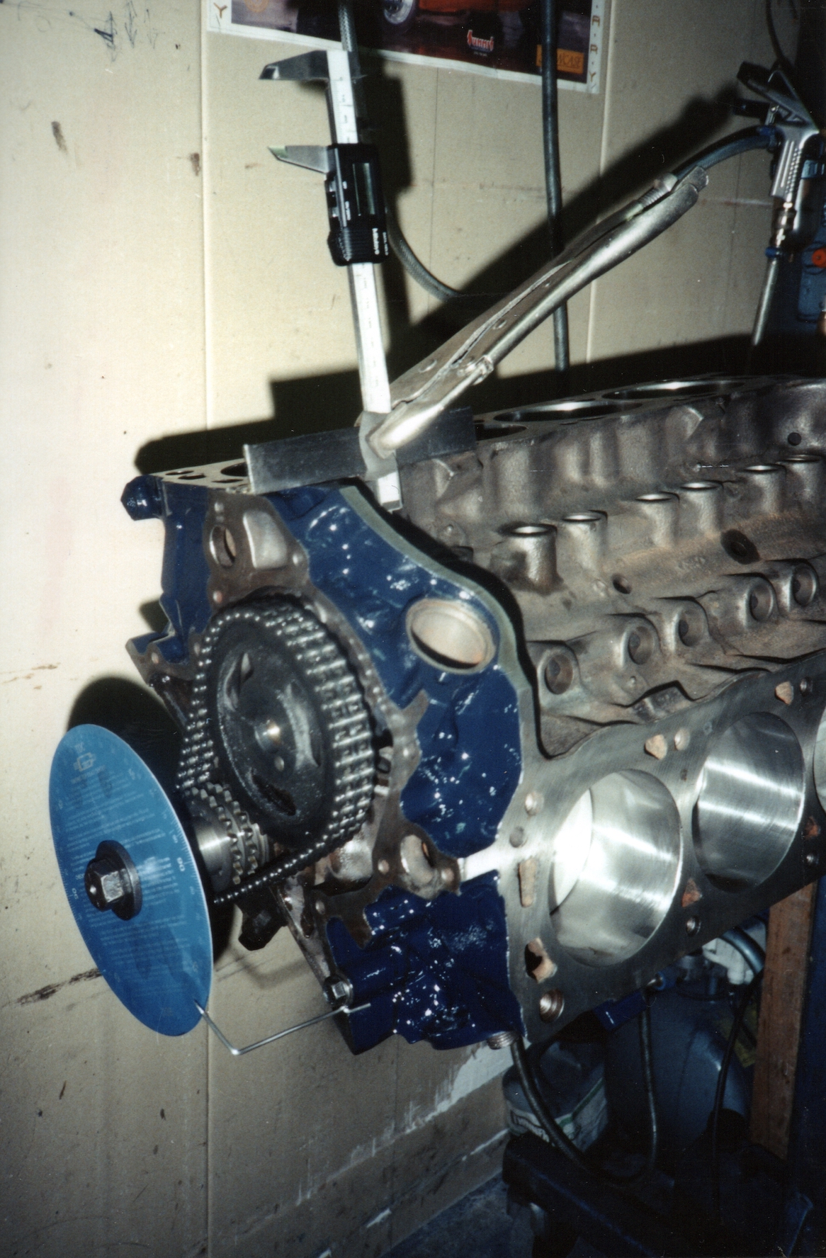
The next step was to fit the timing chain and degree the cam. I used a digital caliper to measure the lift at the cam lifters and a timing disk (the blue thing) on the crank nose. The cam was a 272 degree Crane Energizer, standard hydraulic lifters.


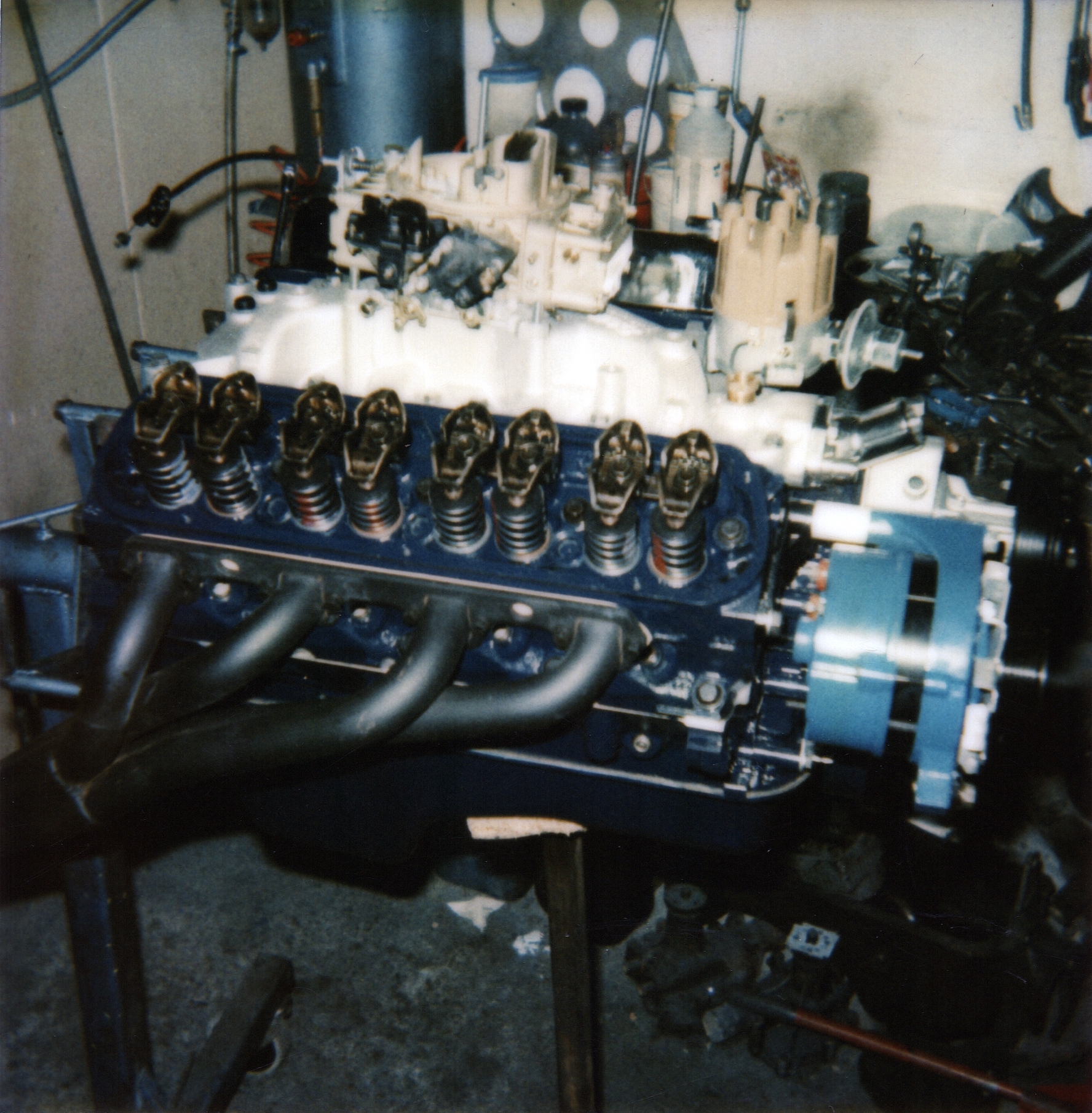
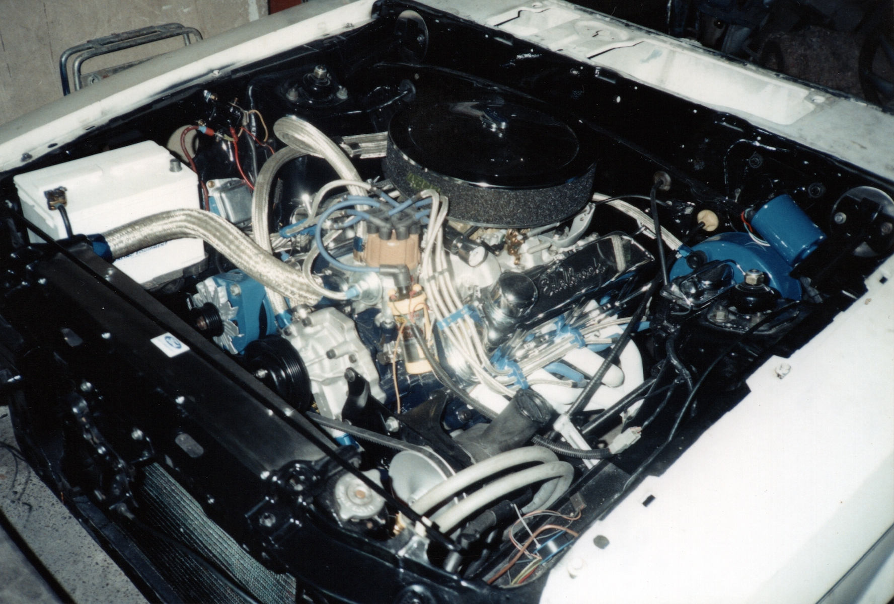
Again gaps in the photo story but the following shows the engine complete with an Accel dual point performance distributor, an Edelbrock manifold and a Holley 4-barrel carb. Keep it simple.

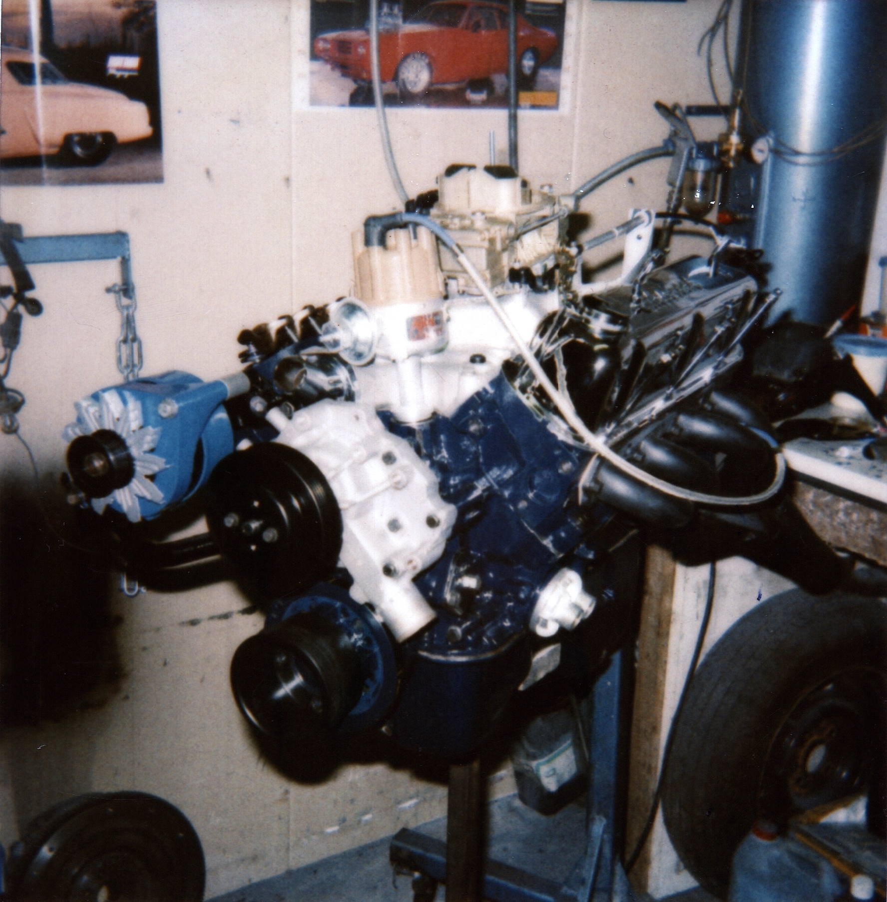
A set of Hooker headers took care of the exhaust gases. A new water pump, recon alternator and a set of Edelbrock valve covers. This was as close to a blueprint motor you could build on a budget back in 1990.

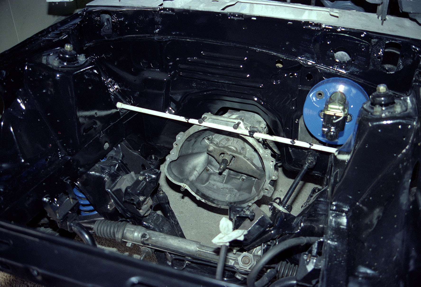
This is the engine bay ready to take the engine, the white rod is just supporting the transmission temporarily.

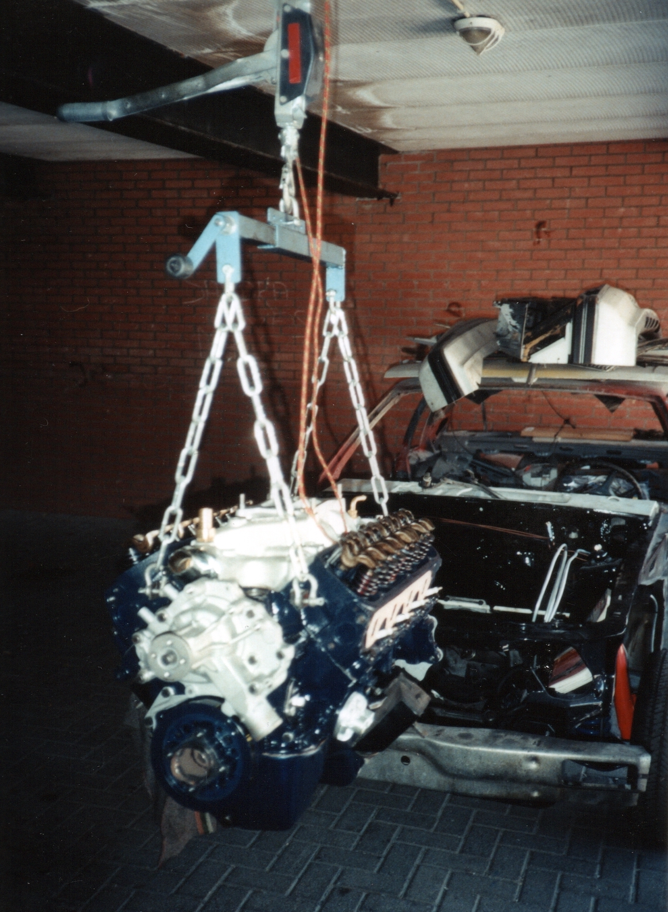
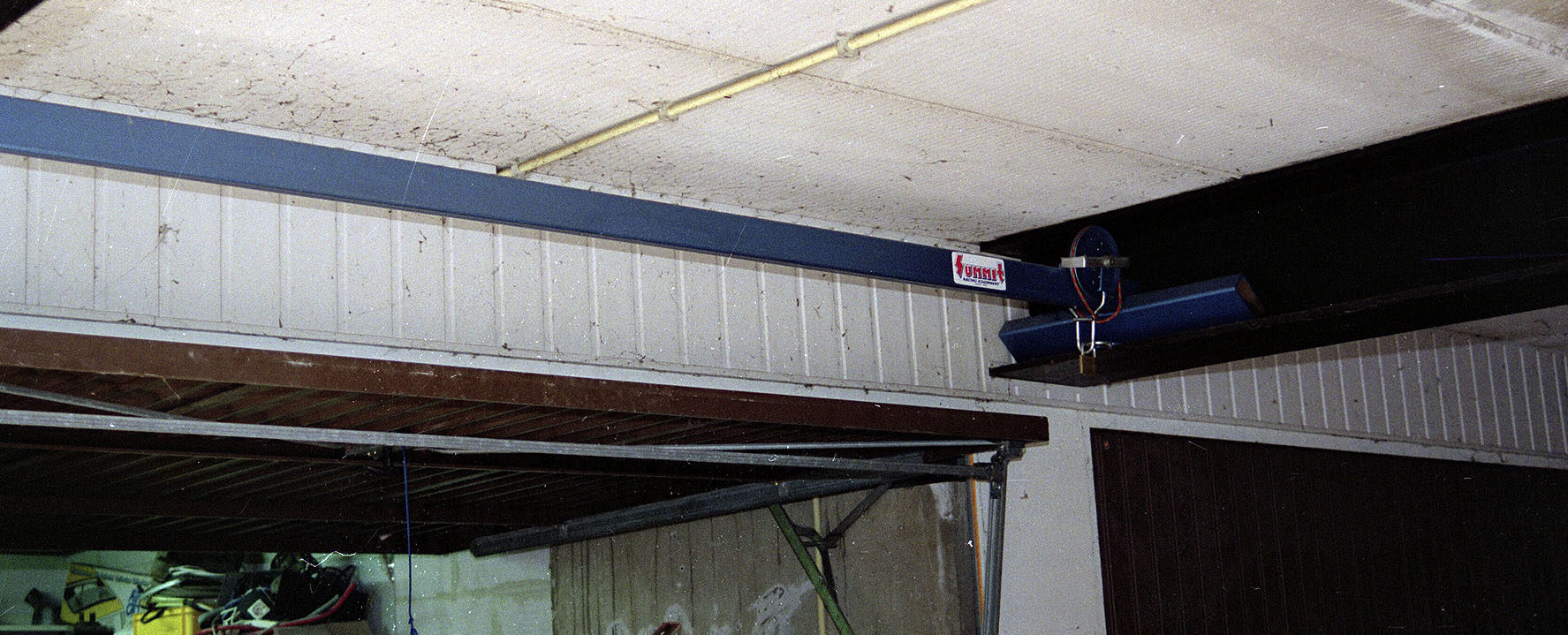
Another bad picture of the engine being installed in the body.  I constructed a sort of gantry which ran between the steel girders supporting the patios of the maisonettes above the garages (see inset picture top right) plus the engine tilter. At least then I could lift the engine in and out without any help (always seem to be working alone). I hadn’t the cash or space for an engine hoist at the time so this was built from all sorts of stuff either lying around or scrounged. Same goes for the engine tilter which I still use today.


The engine installation is finished and I could concentrate on getting the car sprayed.

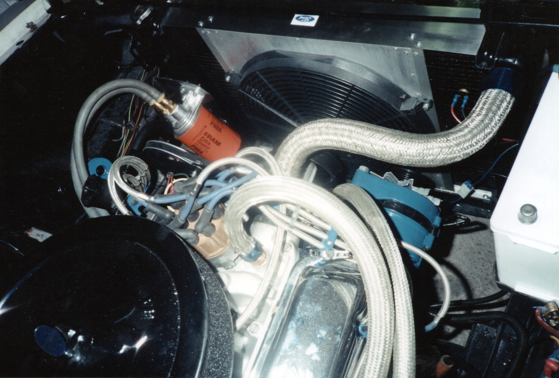
Another shot showing an uprated custom built triple row radiator, fitted with a high flow electrical fan to deal with the extra heat generated in a tuned motor.

Next: Mustang – Part 3


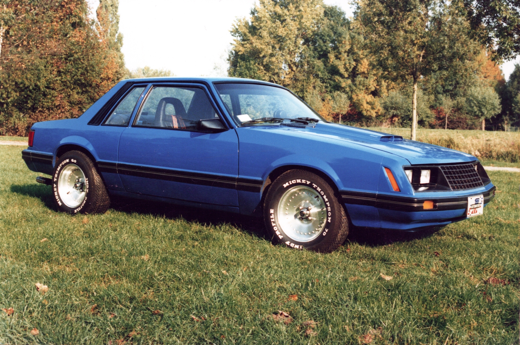
I bought the Mustang in 1989 after looking round for a project. Although I really like the 60’s Mustangs the prices being asked in Holland at the time were a bit extreme especially when a lot of them were real basket cases. I settled on a Mustang 3 Ghia from 1979 which I found by a dealer in Katwijk, it wasn’t in the best condition but it had a 302ci small block V8 (5.0L) and a 4-speed manual box and I didn’t pay much for it. I drove it for a while but it was a bit of a slouch and smoked a little, the engine compartment was also a real mess with a lot of the environmental things not working effectively. To be honest the sort of additions that were used in the US at the time were BS. So eventually I decided that there was only one thing to do – a complete custom restoration. The photo above was taken in ’96 if I remember correctly, after I had imported a set of Centerline Racing Alloys and Mickey Thompson Indy Profile retro tyres. It didn’t always look like this though.

From the time that the car was first finished in ’91 we used to attend a lot of meetings. The car was built with drag racing in mind but I wanted it to be street legal, it was therefore never a particularly comfortable car to drive long distances. Through the summer seasons the most popular meeting on the American Car scene in the Netherlands was the Saturday Night Cruise in Scheveningen near The Hague. It wasn’t much more than a number of cars parked in a small industrial park near the harbour and sea front but you needed to be there early to be sure of a place. During the evening cars would leave now and then to cruise up and down the boulevard while somebody else kept your place free until you returned. To be honest the number of people who actually built cars and maintained them like I do could be counted on your hands and although we had some interesting discussions with these guys most of the time I was explaining to others why and how certain things were done. Trying to share knowledge. You tend to stand out as a non-national (foreigner) and I believe I got a bit of a reputation for having the ‘knowledge’. Sometimes guys with a particular problem with their car would come over and tell me they had been told to go and talk to the English guy with the blue Mustang.

Some years later the local council decided to close down the meeting due to nuisance being caused on the boulevard by people with old American shit that wasn’t welcome at the meet. We were moved to an industrial park somewhere else in the town which was nowhere as much fun so I eventually stopped going. By the time I bought the BMW in ’98 I was just about done with the American Car scene but it would be another three years before I found a buyer for the ‘Stang.


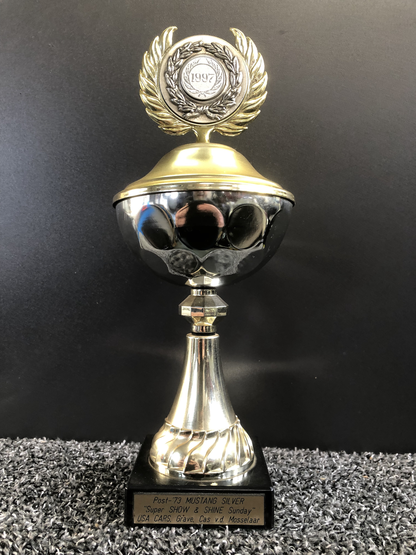
Above is the trophy I won at the Show’n’Shine Sunday meeting we attended in Arnhem in 1997, it was for the class Post ’73 Mustang. It was quite unexpected as I don’t attend these meetings with any attention to try and win something, it’s just a way of showing what I do and talking to others about it. We had arrived quite early on the Sunday morning and were quite close to the main show area. I spent the first hour or so doing a little polishing to get rid of the dead flies we’d picked up on the way. Then we spent some time talking to people who stopped to look at the car and meeting old friends who had also arrived. We then left the car to go and inspect the other cars, which turned out to be quite a lot as they had spread into two more fields after we arrived. We also spent some time by the food and drink in the main show area. when we got back to the car a little later there was a card under one of the windshield wipers informing me that the judges had been around and had selected the car for the final of the prize-giving. It was a pity I’d missed them as I could have told them about how and why I had done the work on the car. I didn’t think any more about it until later in the afternoon while I was in discussion with another owner when someone came over to tell me that he was certain that the car had been named during the prize-giving and that maybe I should get over to the main stand to enquire. To be honest I wasn’t even aware that it was taking place and by the time I got over there they had finished the ceremony and were packing up to go home. I told them that I was the owner of the car and they fetched the cup out of one of the boxes and sort of presented it to me. Shame we missed the main event

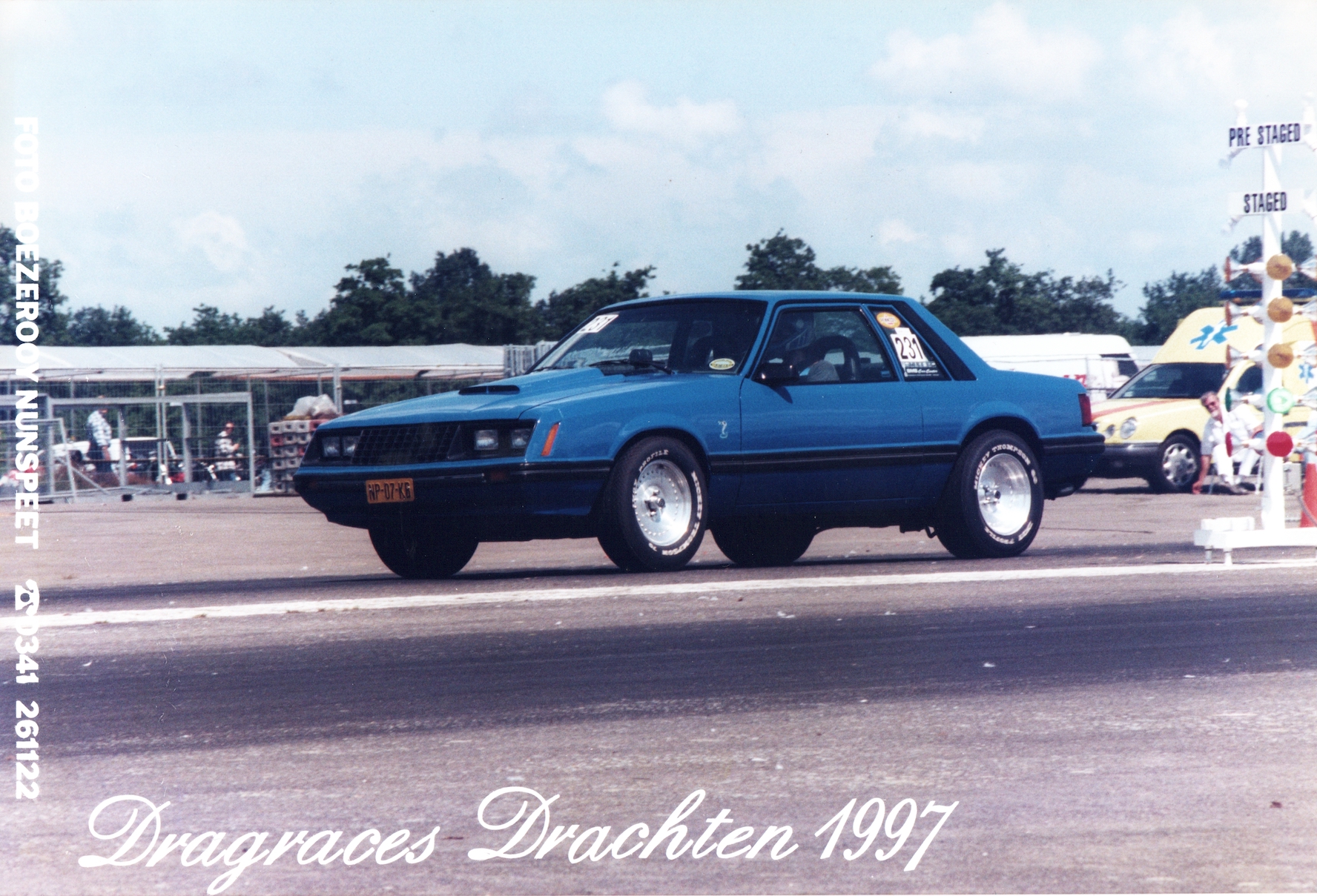
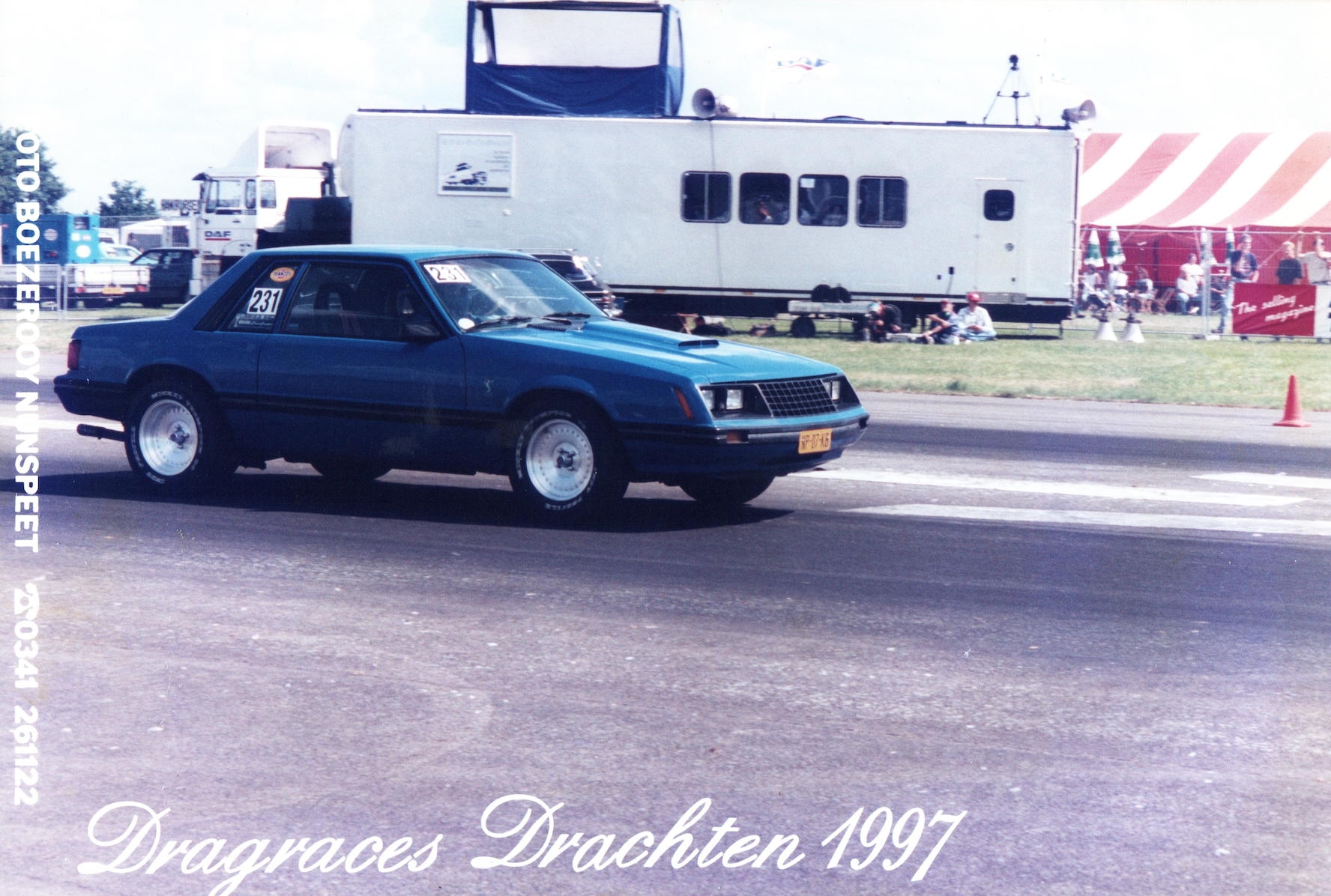
A week after the Show’n’Shine Sunday there was a drag race meeting in Drachten in the north of the country. I went up on my own with a tent packed in the back of the car planning to meet some other guys I knew from the American Car circuit. On the Saturday was qualifying and the eliminations took place on the Sunday. It wasn’t a bad weekend, the weather was perfect, unlike weather I have experienced at Santa Pod Raceway in the UK in the past. But unlike Santa Pod it wasn’t that well organised. Due to restrictions on the event times enforced by the local authorities it made the days quite short and so everything was extremely rushed. Another thing was that it took place on an airfield which was itself not too large and it was not possible to let the faster cars run any more than 1/8th mile instead of the usual 1/4 mile. The class I ran is was ‘Street’ which just about covered everything that was legally allowed on the road and therefore encompassed a pretty wide spread of ET’s (elapsed time). As they were just running heads up racing as opposed to a handicap system it meant that the chance of doing any good was pretty small. There was actually a pretty large entry for the class, about 25 cars or so, and after a couple of practice runs I managed to qualify 13th which wasn’t too bad. During qualifying it became obvious to me that nearly all of the competitors had arrived with the car on a trailer and a lot of them were running cheater slicks. Cheater slicks were a tyre you could buy in the US which were basically slicks with a couple of shallow tread grooves cut in them and a DOT (Dept. of Transport) approved stamp. Having a short life they were not what you’d normally use on the road, just racing. I had arrived fully road legal with genuine road tyres so I was at a disadvantage from the start. On the timing slips it was obvious I was losing out in the first 60 foot, as I couldn’t get enough grip. A simple burn out was not enough to get the street tyres sticky. In the eliminations on the Sunday following the normal rules with a 16 car field meant that I would be up against the number 4 qualifier and as it was heads up racing I didn’t stand much chance. I got beaten off the line, as was to be expected, but by half track I was catching him up but couldn’t do it before we crossed the line. It wasn’t bad considering it was the first time the car had been raced, this not including all the traffic light duels I had with boy racers in hot hatches running around our home town.

Mustang - Part 1

Mustang - Part 1

After starting to strip it down I found that the factory sunroof was completely rotten and unrepairable, the only answer was a new roof. So a new roof was sourced from a scrap yard and the delicate process of cutting off the old one was started. The ...
Mustang - Part 2

Mustang - Part 2

It was a bit of a puzzle to get everything to fit in the garage after I had stripped the car. Here you can see the block stripped down on the engine stand with rear axle and front subframe on the floor under the bench.     I eventually...
Mustang - Part 3

Mustang - Part 3

Plastic nose masked up whilst the primer was applied. Did all this work in the covered area just outside my garage box until the Environmental Police paid me a visit - OOPS!   Black mist coat applied to aid with wet sanding of the primer....


The original MAF Casing as shown at the top of the webpages was OK and seemed to attract enough attention at meetings but I had other ideas floating around in my head. It needed to match the engine more closely and how could I produce it. Eventually end of last year I had some drawings in Autodesk Inventor finished and was speaking to a neighbour of mine with a CNC machine about machining it from a block of aluminium. Unfortunately the finished drawing model turned out to be about 1.3 kilos, so it was back to the drawing board.

Too busy early in the season to do much work on it but the last few weeks I put on a spurt to finish it for the Santa Pod BMW event on the last weekend of September 2015. It’s now been fabricated on my milling machine from separate aluminium sections epoxied around the Bosch sensor tube with the sensor itself plugged in the back in the same way. There are some more descriptions with the photos.

  • Mini Mill setup to machine the parts

The problem:

The problem is well  known within the e24 community, and probably other models but I don’t keep up with everything. Above a certain speed the orange ABS warning light comes on and although the brakes work OK the ABS assistance is turned off. The simple (and I mean simple as in not-so-intelligent) solution that I have seen on occasions suggested in fora is to remove the warning lamp. I had the problem for a number of years but only by fairly high speed levels, but the last couple of years it had started to happen under 100 kph so something had to be done.

A little theory:

An ABS system includes a central electronic control unit (ECU), four wheel speed sensors, and valves within the brake hydraulics. The ECU constantly monitors the rotational speed of each wheel; if it detects a wheel rotating significantly slower than the others, a condition indicative of impending wheel lock, it actuates the valves to reduce hydraulic pressure to the brake at the affected wheel, thus reducing the braking force on that wheel; the wheel then turns faster. Conversely, if the ECU detects a wheel turning significantly faster than the others, brake hydraulic pressure to the wheel is increased so the braking force is reapplied, slowing down the wheel. This process is repeated continuously and can be detected by the driver via brake pedal pulsation. The ECU is programmed to disregard differences in wheel rotative speed below a critical threshold, because when the car is turning, the two wheels towards the centre of the curve turn slower than the outer two. If a fault develops in any part of the ABS, a warning light will usually be illuminated on the vehicle instrument panel, and the ABS will be disabled until the fault is rectified.

The most common ABS problems are related to the sensors and the tone wheels in the hubs which are used to measure the rotational speed of the wheel. The sensors on most vehicles are magnetic and generate an alternating current (AC) signal that increases in frequency and amplitude with wheel speed. These are sometimes called “variable reluctance” (VR) or “passive” WSS sensors because they generate their own voltage signal when the vehicle is in motion. They have two wires: signal and ground.

Inside a passive WSS sensor is a permanent magnet core surrounded by copper wire windings. When the teeth on the tone ring rotate past the sensor tip, it changes the magnetic field and induces a current in the sensor windings. The result is a classic sine wave current pattern that changes with wheel speed. Since the voltage induced in the sensor is a result of the rotating wheel, this sensor can become inaccurate at slow speeds. The slower rotation of the wheel can cause inaccurate fluctuations in the magnetic field and thus cause inaccurate readings to the controller.

Traceable faults:

The sensors can malfunction but the basic functionality can be tested by connecting an ohmmeter across its terminals. The resistance specs will vary depending on the application, but most sensors should read between 450 and 2200 ohms (always look up the exact specifications because they can vary a great deal from one vehicle application to another). If a sensor reads open, shorted or is out of spec, it can’t generate an accurate signal and must be replaced. You can also test the sensor’s output by spinning the tyre by hand at a rate of about one revolution per second. With a voltmeter attached to the sensor’s terminals, a good sensor should generate between 50 and 700 millivolts AC. Other situations can occur due to metallic debris and dirt sticking to the magnetic tip of the sensor or degradation of the tone wheel affecting the air gap or the quality of the generated magnetic field.

My solution:

Although never having had an electrical problem with the sensors I have had to replace them as they had become rusted solid in the hub carrier when I refurbished the rear axle and front suspension assemblies. The tone wheels are another problem area and this where I used a little ingenuity and my workshop facility to solve the problem. The front tone wheels are easily accessible as they are relatively exposed on the hub and are as such easy to keep clean. The rears are very difficult to access as they sit deep inside the trailing arm mounted on the hub installed in the wheel bearings. As mine where untouched for 25 years they had deteriorated to the extent that there was very little left of the teeth. You can see this in the slide show at the bottom. To actually get at them means removing the drive (half) shafts so you can get at the drive flange which is fastened to the stub axle with a large nut. To remove this (and to replace it) you need a very large (torque) wrench. Once removed the state of the teeth was obviously the cause of the problem so I made enquiries at the dealer for replacements. The drive flanges are only sold complete, it is not possible to just buy the toothed tone wheel and so it starts to get expensive (€175,- each side).

In the slide show you can see that I turned the tone wheels off the flange and so found that they are separate parts. I made my own replacements by buying a short length of 70mm dia round steel bar for €20 and hollowing it out on the lathe deep enough to give me the two rings I needed. Next stage was to transfer it to the milling machine to cut the teeth. This meant setting it up between a rotary table and mini tailstock so that I could cut the teeth at the correct places on the circumference of the steel bar. I had counted the old teeth and needed 95, resulting in a spacing of 3.789 degrees between each tooth, so I created a spreadsheet to work out the degrees for each increment between 0 and 360. I have to confess that I needed 2 attempts to get it right as the first attempt was based on the assumption that the teeth were pointed like a normal gear wheel. Looking at the old ones it did seem like that as the teeth were so badly eaten away. So anyway I cut them with an angled cutter as you can see from the photo and re-assembled everything to find that it didn’t work. For the second attempt the teeth were cut with a 1mm slitting saw and this gave the correct profile for the pulse to be generated by the sensors. After re-assembling again I tested it and everything was OK, that was even the case when driving on the autobahn in Germany in 2013 at 200+ kph.

Now although this seems like a significant cost saving it has to be remembered that a) you need the workshop facilities and b) you don’t need to cost the time spent doing it. It gives you a tremendous amount of satisfaction to create something like this but it isn’t something you would do as a commercial undertaking, unless BMW stop producing the spares of course.

Next: New Instrument Panel

The one major area needing attention after the engine rebuild was the rear axle. All the various suspension rubbers were in pretty poor condition and had been on my list for some time. I decided that while the rear axle was out I would also fit a mild lowering kit and uprate the braking.

The first job was to remove the rear section of the exhaust, drive shaft, fuel tank, axle shafts, rear suspension struts and the trailing arms. The rear struts were discarded (well I say discarded, they were in pretty good condition and were put up for sale) as they would be replaced with the lowering kit. The differential was removed from the rear axle carrier which was then dropped out and I set about removing the old rubber bushes. There was very little over from the large rubber mounting bushes in the axle carrier, also the bushes in the trailing arms weren’t shot but needed replacing. Because they had been in for so long even a hydraulic press wouldn’t shift them, so I got the acetylene torch out and got them nice and hot 🙂 ,  most of the rubber burnt out through this process however and the workshop was full of smoke. It did manage to release them and they pressed out OK after that. The subframe, the trailing  arms and the brake backing plates were then sent away to be blasted and powder coated.

While those parts were away I got on with some other work.

Axle shafts and CV Joints
The CV joints from the axle shafts were dismantled, degreased and thoroughly inspected for wear. They were in surprisingly good condition considering the age, there were no splits or leaks in the boots, although the grease was starting to dry out, and no wear on the surface of the grooves where the balls are held. To dismantle them you need a system to mark and store the parts so that they can be put back together in exactly the same position, so I usually create some kind of tray from a cardboard box where I can make cut outs to place everything as it came out. The shafts were giving a coat of protective paint and then using a rebuild set new boots were installed. The CV joints were reassembled and filled with the correct amount of grease as supplied in the kit. I then finished it off with new set of boot clamps.

Brakes
Although not bad the brakes needed to be uprated  a little to compensate for the extra performance from the Miller MAF conversion. After researching various options and having realised that the budget was not a bottomless pit I decided to replace just the front discs and calipers with a set from an e32 740i. These are a little larger in diameter and substantially thicker. The calipers I bought used but the discs were new as most used discs have no meat on them anyway. While the rear calipers were also off I had the whole set blasted and then treated them with heat resistant caliper paint. They were then reassembled with a repair kit. The e32 discs are a straight fit on the e24 front stub axles and fit millimetre perfect within the shape of the backing plate. When you think about it the e24 disc seems a bit small for the plate. Brakes were reassembled and finished off with a set of Goodridge SS brake lines.

Fuel tank, pump and filter
The tank was in good condition and also surprisingly clean inside. After removing the lift pump (which had been replaced a couple of years earlier) it was washed out and given a coat of protective paint and underbody coating. Filter was replaced, of course, and the main pump was dismantled to see if it was clean and intact inside. For the re-assembly I used new rubber piping and new rubber isolation mounts as the old stuff was no longer serviceable.

While this whole underbody area was exposed I took the opportunity to inspect it for any signs of rust forming or deterioration of the underbody coating. I gave some sensitive areas another coat just to be sure.

Rear axle carrier and suspension re-assembly
The axle carrier was fitted with new rubber mountings, and the trailing arms with new rubber bushes, using my neighbour’s hydraulic press. Axle carrier was lifted into position and re-attached. The differential which had been cleaned up and painted was then fitted and the drive shaft installed. Wheel bearings were refitted in the trailing arms which were then re-attached and loosely tightened. They would be torqued up later on a lift with some extra weight in the car to set the suspension at the correct height. The new suspension parts were fitted followed by the refurbished brakes and brake lines. The last piece in the puzzle was the rear section of the exhaust and we were ready to fire it up again and test it.

Generally speaking a rebuild with new or serviced parts is pretty straightforward and this time was no different.

Below is a slideshow of some of the refurbished parts prior to and during installation.

Next: ABS warning repair